TNR Hardware
This page describes the TNR hardware (as much as I know).
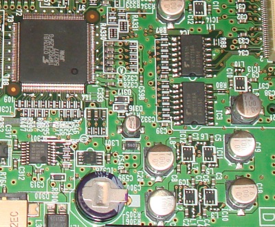
Teardown
A teardown of a TNR-W can be found here at bunnie’s blog. I really didn’t want to take mine apart!
Service manual
The service manual is a fantastic resource for identifying how the peripherals are actually connected to the CPU, and therefore what the various registers are actually doing. This has been my main route of investigation into the software : for example, the service manual identifies that the MIDI connector is attached to pins 126 and 127 of the CPU. Looking up these pins in the CPU datasheet tells us that these are Ports F0 and F1, located at 0x003C in the memory map. Consequently, any code accessing 0x003C is to do with handling MIDI.
The service manual for the TNR-O (the orange version) can be found on-line.
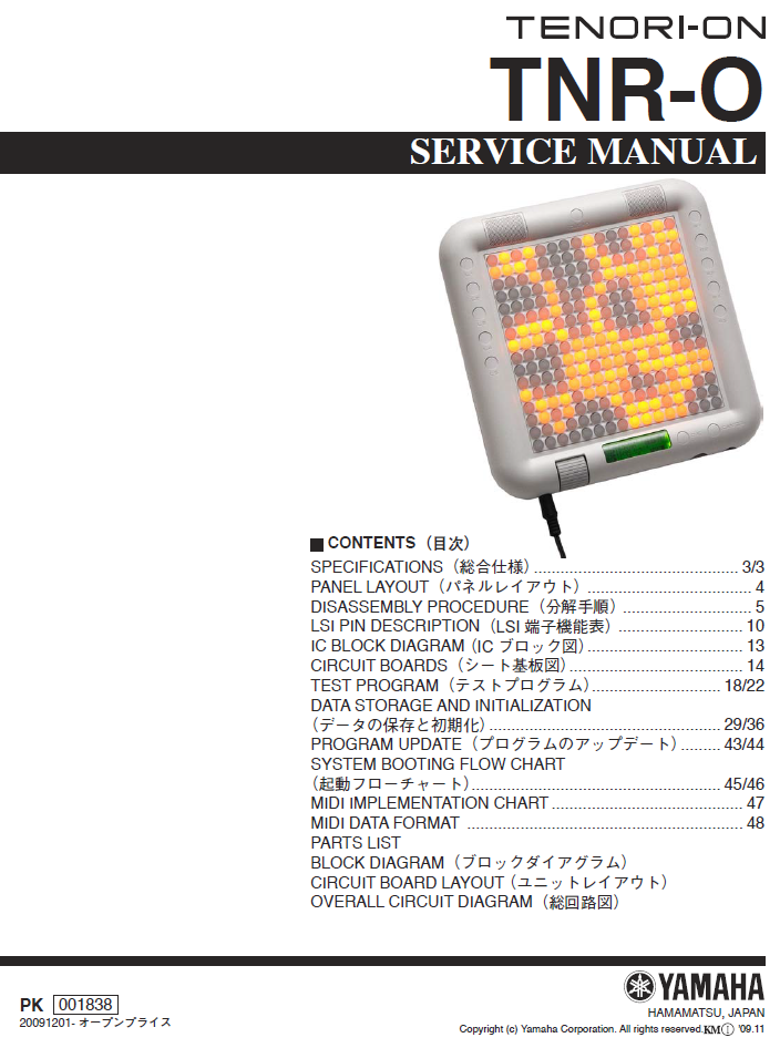
It is in both Japanese and English. The service manual for the TNR-W is almost identical. While there are several differences between the TNR-W and the TNR-O (colour, backside LEDs, battery), the schematics in the service manual for the TNR-O just show the TNR-W components with a dotted line saying “not fitted”. Similarly to the actual hardware, the service manual is really fantastic, and provides so much good information for wannabe Tenori-on modders.
CPU : Toshiba TLCS-900/H1 : TMP92CA25FG
The CPU is a now-discontinued Toshiba microcontroller, with quite a lot of useful inbuilt interfaces. Useful documents include the datasheet and the CPU instruction set manual . The best bit of the manual is chapter 3.
Finding a compiler/disassembler/assembler for this however is hard. Toshiba sell a commercial one, but it is expensive (~500 €).
For disassemblers, by an amazing coincidence, this is the same processor as used on the Neo Geo Pocket Color, a hand held video game console made by the now defunct SNK. Like many retro games, this has a bit of a emulator community, and I found that the Neopop emulator code included a TLCS disassembler. Also, github hosts a python based TLCS 900 disassembler from user Victorious3.
The commercial IDA disassembler from Hex-Rays also includes support for the TLCS-900, I believe as a module that you need to compile using the IDA SDK.
I am reassembling using the excellent Macro Assembler AS. When I couldn’t get binary-identical reassembly for the 2.10 branch, Alfred - the developer of the assembler - made some specific enhancements to AS which enabled me to generate identical code, so much thanks to him.
“Tone Generator” : Yamaha SWL-01 : YMW767-VTZ : X6055A00
There is almost no documentation on this device. This is a custom Yamaha sound chip from 2002, used in the following contemporaneous Yamaha products, as confirmed by their service manuals:
- CP-33 Stage piano
- DD-65/YDD-60 Digital percussion
- DGX-620/YPG-625 Portable Grand
- EZ-200/EZ-J200 Portatone
- KB-180/SKB-180 Digital Keyboard
- PSR-E213/YPT-210 Portatone
- PSR-VN300 Portatone
(If anyone has any dumped firmware from these devices, please get in touch).
It is not quite the same device as all the products attributed to the SWL01 in this list but there are many similar features.
It is actually based on an ARM7TDMI core, and operates as a second CPU connected to a DSP. In this respect it is similar to the Yamaha AICA chip used in the Sega Dreamcast, also from 2002; the dumped firmware running on the SWL-01 bears some similarities with the “Manatee” drivers present in Dreamcast games. (Thanks to Alex and the Dreamcast community for helping me here!)
It has a small amount of local register space for the DSP, and is attached to a block of Flash ROM (TC58FVM7 B5BTG65CCH, 128Mbit) for both the running program, and the on-board sounds.
The TLCS-900 and SWL-01 communicate over the address and data bus, the SWL-01 is memory mapped into the TLCS-900 address space. However, the Flash memory, used for storing the instruments and user samples, is only accessible by the SWL; updating the user samples involves the TLCS-900 messaging the SWL, which then writes to its Flash memory - this is why updating user samples takes so long.
The Tone generator software running on the SWL01 is relatively safely updatable since unlike the Boot software on the TLCS it isn’t responsible for its own patching. However I haven’t managed to reassemble an image from source code yet, so modifications to the SWL01 code will have to wait.
LCD Module : WG12232D-YGH
I couldn’t find much useful on this directly, but it includes (most likely a pair of) Avant SBN1661G LCD controllers (1⁄32 duty cycle), running 122x32 dots. Datasheets on the SBN1661G controller exist that help understand how it is being driven. This is controlled via specific IO ports on the TLCS-900.
Memory
Various blocks of memory are memory mapped onto the CPU’s address bus. The memory mapping is set up by the boot code, and I haven’t managed to work out how to dump an image to an SD card yet, so can’t quite tell for sure how it is configured.
- There is some Flash memory : S29JL032H 70TFI010 (32Mbit device) : accessible by the TLCS CPU.
- There is 16Mbit of SDRAM fitted; the schematic lists this as W9816GCH-7. This would be 143MHz/CL3. The parts list indicates it could also be W98G6IH-7 (which looks very similar) or even IS42S16100E-7TL. the schematic also indicates a further lump of RAM (M12L64164A) with the helpful label “Not installed” and “For the future”.
The Tone generator’s Flash ROM is not memory mapped into the TLCS address space.
DAC
The digital-to-analog converter (that makes the audio sound) is an AsahiKASEI AK4385 24bit, up-tp-192kHz DAC. This is attached to the Tone generator directly.